
Features
Designed to complement the S201 Steam Generator and ServiceModule
Stabilises in minutes and allows rapid data collection.
Bench top unit allaws similar experimental procedures to full sizeplant.
Low running and maintenance costs
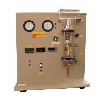
Description
The S211 Steam Turbine Module is compact and incorporates a smallaxial flow impulse steam turbine, a water cooled friction brake, a watercooled condenser and all the necessary controls and instrumentation. ltis designed to be connected to the s201 from which it obtains its supplyof steam and to which it rejects air and condensate. Together the S201 and S211 form a Complete Rankine Cycle Steam turbine with sub-atmospheric condenser.Steam from the S201 Steam Generator andService Module enters through the left-hand end face, passing througha solenoid valve and a throttle valve before entering the turbine nozzle.The turbine shaft is mounted vertically and runs in sealed ball bearings.lt is fitted with a gland to reduce the ingress of air when the turbine isexhausting below atmospheric pressure.The turbine rotor is positioned at the lower end of the shaft and the brake is at the upper end.Theturbine is of the single stage, axial flow impulse (De Laval) type and hasa single convergent-divergent nozzle to expand the steam. After passing through the rotor blades the steam flows directly into a glasswalled water cooled condenser. At the bottom of the condenser is adiverter valve which has two positions. In one position both air andcondensate from the turbine condenser are returned to the dump condenser of the S201. In the other position, air only is returned to thes201 and the condensate is retained in the turbine condenser. In thisway the steam consumption of the turbine may be measured directly byvolume.The brake drum at the upper end of the shaft runs against abelt which is tensioned by a pulley moved by the load adjuster to varythe frictional resistance.The frictional force is measured by a load celland is displayed by a digital meter on the panel. Water for cooling thebrake drum is supplied to a fitting at the top of the shaft and is latercollected and drained away as it leaves the periphery of the drum.Anoptical sensor senses the rotational speed of the turbine and this isdisplayed by a digital tachometer on the panel.
Related Laws/Applications
Thermodynamics
Heat Transfer
Chemical Engineering
Mechanical Engineering
Power Engineering
Marine Engineering
Plant and Process Engineering
Learning capabilities
Determination of torque, power and specific steam consumptionwhen operating: - at constant inlet pressure but with varying exhaustpressure - at constant exhaust pressure but with varying inlet pressure
Determination of power to heat ratio when used as a back pressureturbine.
Determination of friction losses at various exhaust pressures.
Determination of lsentropic Efficiency.
Determination of Thermal Efficiency.