
● Demonstrates all processes found in a full scale forced draught cooling tower
● Rapid stabilisation allows experimental work to commence immediately upon switching on
● Columns with varying packing densities available as optional extras. Optional Packing Characteristics Column also available
● Can be linked to External Loads of up to 1.5 kW including the R515 Mechanical Heat Pump or R833 Air and Water Heat Pump via an intermediate reservoir system
● Two year warranty
Introduction
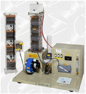
The Hilton Bench Top Cooling Tower has been designed to meet the demand for a compact cooling tower which clearly demonstrates all the processes found in a full size forced draught cooling tower and behaves in a representative manner.
Supplied with standard column B, a number of additional columns are available as optional extras to cope with a wide variety of educational needs in the study of Thermodynamics, Heat and Mass Transfer, Refrigeration and Air Conditioning.
The unit will be of particular interest to those studying:
Building Services
Chemical Engineering
Energy Transfer and Conservation
Mechanical Engineering
Mining Engineering
Plant and Process Engineering
Experimental Capabilities
Basic Unit with Column B
Observation of water flow pattern and distribution.
Measurement of all “end states”, and rates of flow of water, air and make-up.
Plotting of end states on a psychrometric chart and the application of the steady flow equation to draw up energy balances.
Investigation of performance at,
(a) A range of process cooling loads.
(b) A range of inlet temperatures.
ADDITIONAL COLUMNS (Optional)
Columns A and/or C
Investigation of effect of the packing surface area/volume ratio on,
(a) Cooled water temperature approach to wet bulb temperature at inlet to column.
(b) Pressure drop across packing
Column D (Empty Column)
Investigation of performance of locally designed and manufactured packing (student projects).
Column E (Packing Characteristics Column)
Enables air and water properties to be measured at three stations within the packing.
Provides data for the construction of enthalpy driving force diagrams.
Determination of the Characteristics Equation for the packing.
Description
BASIC UNIT
Water Circuit
Warm water is pumped from the load tank through the control valve and water flow meter to the column cap where its temperature is measured. The water is uniformly distributed over the top packing deck and, as it spreads over the plates, a large thin film of water is exposed to the air stream. During its downward passage through the packing, the water is cooled, largely by the evaporation of a small portion of the total flow.
The cooled water falls from the lowest packing deck into the basin, from where it flows past a thermocouple and into the load tank where it is re-heated for re-circulation.
Due to evaporation, the level of the water in the load tank slowly falls. This causes the float operated needle valve to open and transfer water from the make-up tank into the load tank. Under steady conditions, the rate at which the water leaves the make-up tank is equal to the rate of evaporation, plus any small airborne droplets in the air discharge
Air Circuit
Air from the atmosphere, pre-heated by external means if desired, enters the fan at a rate, which is controlled by the intake damper setting. The fan discharges into the distribution chamber and the air passes wet and dry bulb thermocouples before it enters the packed column. As the air stream flows through the packings, its moisture content increases and the water is cooled. On leaving the top of the column the air passes through the droplet arrester, which traps most of the entrained droplets and returns them to the packings. The air is then discharged to the atmosphere via the air measuring orifice and further wet and dry bulb thermocouples. All of the foregoing may be observed through the transparent structure of the column.
All temperatures are indicated by a digital temperature indicator and thermocouple selector switch.
OPTIONAL ADDITIONAL COLUMNS
Columns A and C
Column B supplied with the basic unit may be quickly replaced by either column A or C. All columns have the same external dimensions, but contain different quantities of packing, so that the effect of packing area upon the performance of the cooling tower may be investigated.
Column D (Empty Column)
This column has no internal fittings or packing and is available so that students can make and investigate the performance of their own packing and water distribution system.
Column E (Packing Characteristics Column)
This is available for those who wish to investigate the way in which the air and water properties change as they pass in opposite directions through the column. From this information, enthalpy driving force diagrams may be constructed and the packing characteristics equation determined.
Column E is similar to column C, but is about 300mm higher. The packing is arranged in four blocks with intermediate spaces in which the water and air dry and wet bulb thermometers are measured by thermocouple sensors. These temperatures are displayed by digital indicator mounted on the side of the column.