
Key features
• Compact, mobile unit
• Works as single-stage, two-stage or two-stage intercooled compressor
• Independently controlled compressor units, both with variable-speed dynamometer drives
• Clear, fully-instrumented control panel with mimic diagram
• Low-noise footprint
• Completely fail-safe operation – interlocks and pressure-relief valves prevent misuse
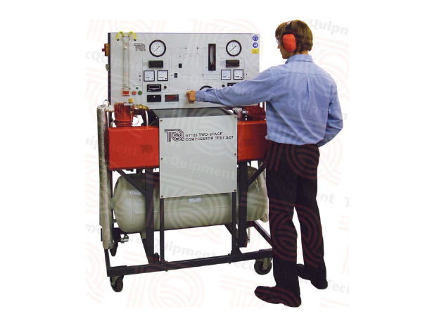
Description
This test set has two independently-controlled, motordriven compressors, intercooler and air receiver. It works as a single-stage, two-stage or two-stage compressor with intercooler. All controls and instrumentation are on an easy-to-operate mimic panel.
Electric motors and low-maintenance toothed belts drive two twin-cylinder, air-cooled reciprocating compressors.
Electronic drive units independently control both motors. Meters show motor electrical power consumption of each motor. A close-coupled load cell on each motor measures torque. A sensor on each motor measures speed, shown by a digital indicator. The product of the torque and speed gives true shaft power.
To allow students to study diff erent types of aircompressor systems, diverter valves allow air to move in diff erent directions. These include:
• From the fi rst stage to the receiver
• Directly to the second stage
• To the second stage, by means of the integral watercooled intercooler
Independent control of the two compressor speeds allows fl exibility to match the two compressors under diff erent conditions. Interlocks allow safe changes from one method of operation to another while the equipment works, and prevent misuse. For safety, all pressurised lines have relief valves.
To help produce pressure and volume diagrams, TecQuipment off ers the optional Pressure Indicator (GT103a). It fi ts to an adaptor on each of the two compressors to measure the pressure changes during a compression cycle. One Pressure Indicator is enough to test each compressor, one at a time. However, you may choose to use two for convenience.
Learning Outcomes
A range of experiments and tests based on:
• Volumetric, mechanical and Isothermal effi ciency
• Indicated work done
• Motor output power (compressor shaft power)
• Pressure ratio • Temperature ratio
• Inlet dryness calculations
• P-V indicator diagram (needs optional pressure indicator)
• Eff ect of inter-stage cooling on compressor total power requirements and eff ect on cycle temperatures
• Eff ect of two-stage compression and inter-stage pressure on power requirements