
Free-standing, mobile apparatus demonstrates pressure losses in several small-bore pipe circuit components, typical of those found in central heating systems.
Key Features
• Mobile, space-saving panel that includes the common pipework parts used in domestic heating systems
• Includes two colour-coded water circuits
• Works with TecQuipment’s Digital Hydraulic Bench (H1F)* for easy installation
• Includes different pipe bends and valves to compare losses
• Fitted with a range of piezometers and a pressure gauge to give accurate pressure measurement
• Optional ‘roughened pipe’ ancillary to investigate flow characteristics in a roughened pipe
Learning Outcomes
A comprehensive range of investigations into losses in a variety of pipes and pipe system components, including:
• Straight pipe loss
• Sudden expansion
• Sudden contraction
• Bends with different radii
• Valves
• Elbows
• Flow in a roughened pipe – needs the optional Roughened Pipe (H16p)
Key Specifications
• Two circuits
• Sudden expansion and contraction
• Gate valve and globe valve
• Elbow
• Mitre bend
• Three smooth 90-degree bends
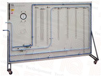
Description
The Losses in Piping Systems apparatus is a vertical panel with two separate hydraulic circuits, colour-coded for clarity. Each circuit includes various pipe system components. The unit has wheels for mobility, which also help when storing the apparatus.
TecQuipment’s Digital Hydraulic Bench (H1F, available separately)* supplies each circuit with a controlled flow of water. This allows students to study flow through the various pipe forms and components, and study and compare the pipe and component characteristics.
The circuits are made of small-bore copper pipe, used in a wide variety of applications such as domestic centralheating systems. The small bore allows the circuits to include many pipe bends and components, while preserving effective upstream and downstream test lengths.
To measure pressure loss across components, the panel includes piezometer tubes and a pressure gauge. The pressure gauge measures pressure loss across valves; the piezometer tubes measure pressure loss across the other components. Included is a hand-pump to adjust the datum position of the piezometers.
Both circuits have common inlet and outlet pipes, controlled by valves. The valves are at the outlet to minimise flow disruption.
TecQuipment offers the optional ‘roughened pipe’. This can fit to the Losses in Piping Systems apparatus or be used by itself (fitted to a wall and connected to a hydraulic bench). It includes a pipe with a roughened internal bore, and pressure tapping points connected to a manometer. The manometer measures the pressure drop due to the pipe. Students compare their experimental results with Moody and Nickuradse charts.
Essential Base Unit
• Digital Hydraulic Bench (H1F)*
*This product will also work with existing TecQuipment Gravimetric and Volumetric Hydraulic Benches (H1 and H1D)