
A cylindrical tank with an adjustable diff user that demonstrates fl ow through diff erent orifi ces for diff erent fl ow rates.
Key Features
• Direct measurement of total head, head loss and diameter of a vertical water jet
• Integral Pitot traverse with blade to measure head in the jet and diameter of jet
• Includes a sharp-edged circular, triangular and square orifi ces. Also converging/diverging, angled entrance and exit, curved entrance (parallel throat) nozzles
• Works with TecQuipment’s Digital Hydraulic Bench (H1F)* for easy installation
Key Specifications
• Includes 13 mm diameter sharp-edged orifice
• Integral Pitot traverse
• Study of the characteristics of different orifices
Learning Outcomes
Investigations into a variety of orifi ces over a range of flow rates, including:
• Determination of contraction and velocity coefficients
• Calculation of discharge coefficient
• Determination of actual discharge coefficient, and comparison with calculated values
• Determination of the various coefficients over a range of flow rates to demonstrate the influence of Reynolds number
• Study of the characteristics of different orifices, using a set of four circular orifices (nozzles). Each has the same minimum throat diameter but a different length. Each has a different approach and discharge section. Also included are additional square and triangular orifices.
Description
TecQuipment’s Flow through an Orifice apparatus allows students to measure:
• Decrease in flow
• Contraction of the stream
• Energy loss
They find these measurements as water leaves an orifice. Students can also use the apparatus to study diff erent shapes of orifice.
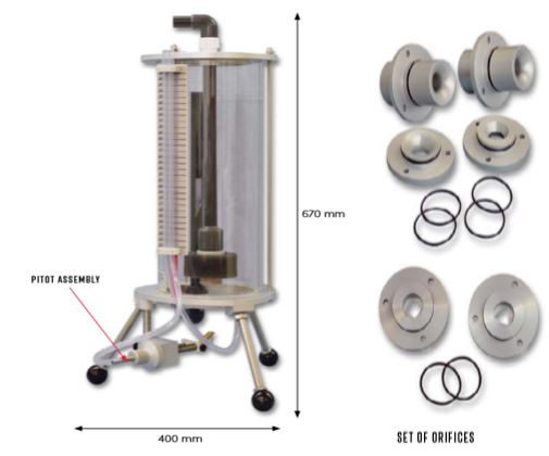
The apparatus works with TecQuipment’s Digital Hydraulic Bench (H1F, available separately)*, and stands on the hydraulic bench worktop. The equipment has a transparent cylindrical tank, with a mounting in the base for diff erent orifices. TecQuipment supplies the apparatus with a sharp-edged orifi ce already mounted.
Water flows from the hydraulic bench and into the cylindrical tank through an adjustable diffuser. The flow rate and an overfl ow pipe set the water level. To change the level in the tank (and so the head on the orifi ce), students adjust the fl ow to the diffuser. Water leaves the tank through the orifice. The jet that leaves the orifice discharges back into the hydraulic bench.
A Pitot assembly holds a sharp blade and a Pitot tube which students can position anywhere in the jet. The blade accurately measures the jet diameter, to allow students to fi nd the contraction coefficient.
Manometers connect to the Pitot tube and a tapping in the base of the cylindrical tank to measure the total head on the orifice and in the jet.
Essential Base Unit
• Digital Hydraulic Bench (H1F)*
*This product will also work with existing TecQuipment Gravimetric and Volumetric Hydraulic Benches (H1 and H1D)